0 序言
一直感觉自己这操作系统学的一点也不扎实:(,果然之前秋招提前批被教育了,所以痛定思痛有了本系列文章,CS之路漫漫兮,吾将上下而求索~
1 背景
1.1 BIOS
BIOS实际上是被固化在计算机ROM(只读存储器)芯片上的一个特殊的软件,为上层软件提供最底层的、最直接的硬件控制与支持。更形象地说,BIOS就是PC计算机硬件与上层软件程序之间的一个”桥梁”,负责访问和控制硬件。(BIOS以系统调用trap的形式提供IO 且 只能存在于系统的实模式下)
1.2 BIOS是如何启动的

首先我们必须明白计算机加电的时候是从哪读出第一条指令的,以x86为例,CPU根据CS(代码段寄存器),IP(指令指针寄存器)的值计算得出PC=16*CS + IP,此时PC为20位的二进制值(因为在实模式下只有20根地址总线,所以只能寻址1MB),在X86架构中 CS:IP 用来表示寻址(这里的PC就是一个概念上的寻址寄存器,实际递增的是IP寄存器),在ARM架构中PC寄存器是存在的(R15),得到地址取出地址中的执行,这条指令是个跳转指令,通过跳转指令跳到BIOS例行程序起始点。BIOS做完计算机硬件自检和初始化后,会选择一个启动设备(例如软盘、硬盘、光盘等),并且读取该设备的第一扇区(即主引导扇区或启动扇区)到内存一个特定的地址0x7c00处,然后CPU控制权会转移到那个地址继续执行。至此BIOS的初始化工作做完了,进一步的工作交给了ucore的bootloader。
1.3 BIOS是如何启动系统的

- BIOS将bootloader(加载程序)从磁盘的主引导扇区(MBR)加载到内存0x7c00
- 跳转到0000(CS):7c00(IP)
- 执行2中地址的bootloader
- 初始化各种寄存器,禁用中断,使能A20(拓宽地址总线宽度),加载GDT,使能cr0进入保护模式,修改保护模式下的各寄存器值,设置堆栈调用bootmain.c
- 加载elf格式的OS
2 分析make生成执行文件的过程
2.1 分析操作系统镜像文件ucore.img是如何一步一步生成的?
1 | // 生成系统镜像 |
2.2 一个被系统认为是符合规范的硬盘主引导扇区的特征是什么?
- 主引导记录MBR的大小为512字节
- MBR结束字为[0x55 0xAA]
在tool/sign.c中可以很清晰的看到MBR的结束标志字(55AA)2字节以及主引导记录大小512字节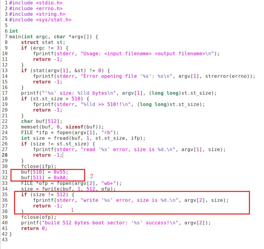
3 调试BIOS的加载
实验步骤如下:
- qemu -hda ucore.img -s -S # 打开qemu并附加参数-s设置连接端口1234
- gdb
- target remote localhost:1234 # gdb连接qemu(也可忽略前三步直接make debug)
- 输入 b *0x7c00设置断点
- continue
- x/i $pc # 查看一条当前的指令
可以看到0x7c00处的代码和bootasm.S处的代码一致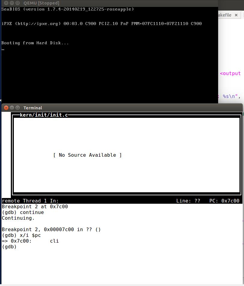
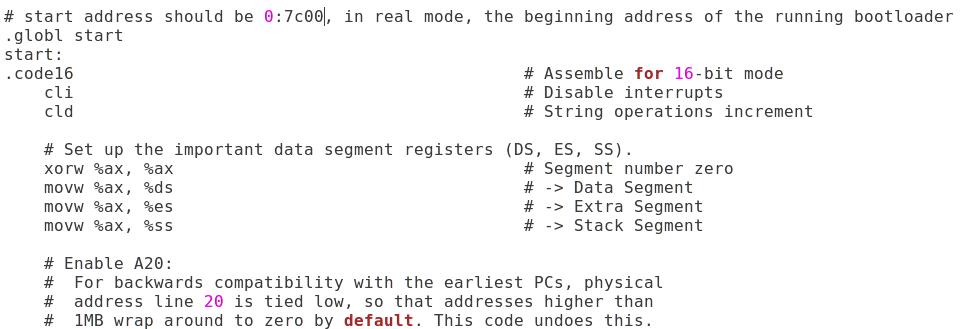
4 分析bootloader进入保护模式的过程
1 | # start address should be 0:7c00, in real mode, the beginning address of the running bootloader |
根据代码注释可以总结得bootloaer进入保护模式的流程为:
- 禁用中断
- 复位标志寄存器
- 初始化ds,es,ss三个段(设置为0)
- 使能A20(扩大寻址空间)
- 跳转到gdtdes中,加载GDT(全局描述符表)
- 使能cr0,切换到保护模式
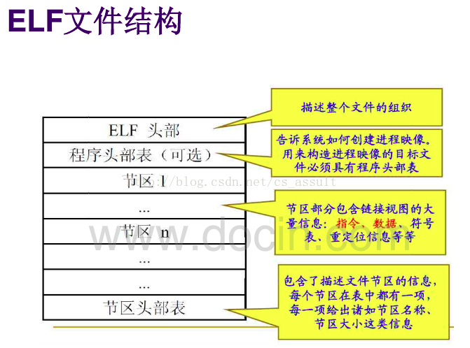
5 分析bootloader加载ELF格式的OS的过程
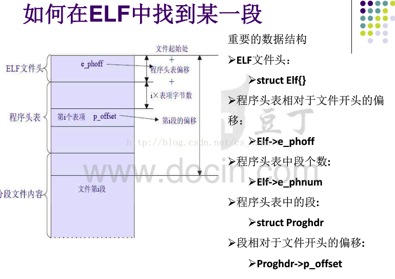
5.2 elf文件格式
5.1 bootloader如何读取硬盘扇区的?
1 | * waitdisk - wait for disk ready */ |
读扇区的流程总结为:
- 等待磁盘准备好
- 写地址0x1f2~0x1f5,0x1f7,发出读取磁盘的命令
- 等待磁盘准备好
- 调用函数insl把扇区数据读到内存
5.2 bootloader是如何加载ELF格式的OS?
1 | /* * |
从源码中可以看出程序控制流:
- 运行bootmain,调用readseg读取多个扇区
- readseg循环执行readsect读取每个扇区
- 返回bootmain,判断elf格式
- 将ELFheader读入ph(pragram header,程序头表)
- 将ph中各个section读入内存
- 通过内核入口函数加载内核
6 实现函数调用堆栈跟踪函数
这里的代码根据注释不难写出。1
2
3
4
5
6
7
8
9
10
11
12
13
14
15
16
17 void print_stackframe(void) {
uint32_t ebp=read_ebp(); //(1) call read_ebp() to get the value of ebp. the type is (uint32_t)
uint32_t eip=read_eip(); //(2) call read_eip() to get the value of eip. the type is (uint32_t)
for(int i=0;i<STACKFRAME_DEPTH&&ebp!=0;i++){ //(3) from 0 .. STACKFRAME_DEPTH
cprintf("ebp:0x%08x eip:0x%08x ",ebp,eip); //(3.1)printf value of ebp, eip
uint32_t *tmp=(uint32_t *)ebp+2;
cprintf("arg :0x%08x 0x%08x 0x%08x 0x%08x",*(tmp+0),*(tmp+1),*(tmp+2),*(tmp+3)); //(3.2)(uint32_t)calling
arguments [0..4] = the contents in address (unit32_t)ebp +2 [0..4]
cprintf("\n"); //(3.3) cprintf("\n");
print_debuginfo(eip-1); //(3.4) call print_debuginfo(eip-1) to print the C calling function name and line
number, etc.
eip=((uint32_t *)ebp)[1];
ebp=((uint32_t *)ebp)[0]; //(3.5) popup a calling stackframe
}
}
运行结果如图所示: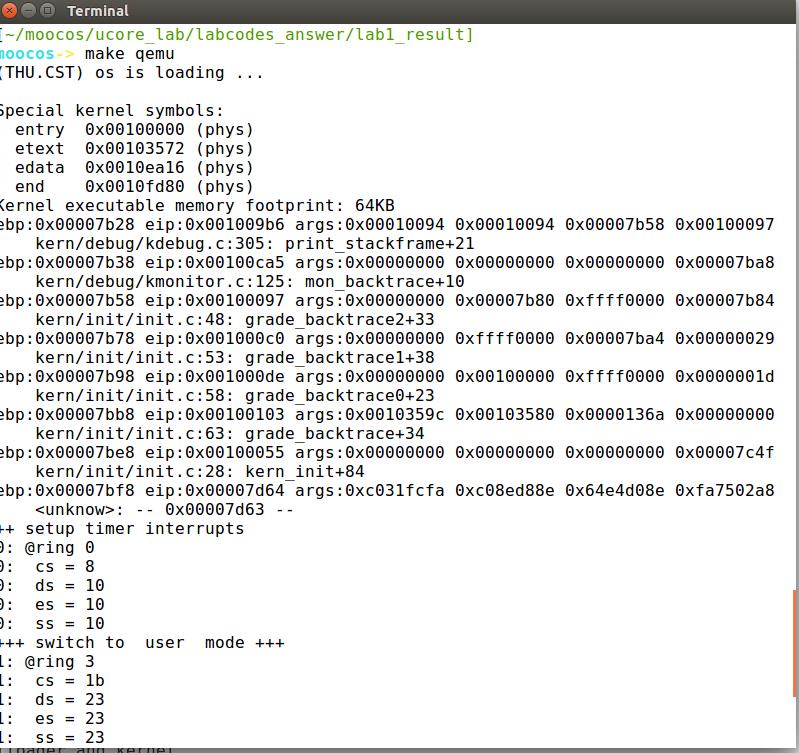
ebp是栈底指针,从该地址为基准,向上(栈底方向)能获取返回地址、参数值,向下(栈顶方向)能获取函数局部变量值,而该地址处又存储着上一层函数调用时的ebp值,eip则是指令指针寄存器保存着下一条指令的地址,最后一行输出的信息是debug_info,查看该函数定义:1
2
3
4
5
6
7
8
9
10
11
12
13
14
15
16void print_debuginfo(uintptr_t eip) {
struct eipdebuginfo info;
if (debuginfo_eip(eip, &info) != 0) {
cprintf(" <unknow>: -- 0x%08x --\n", eip);
}
else {
char fnname[256];
int j;
for (j = 0; j < info.eip_fn_namelen; j ++) {
fnname[j] = info.eip_fn_name[j];
}
fnname[j] = '\0';
cprintf(" %s:%d: %s+%d\n", info.eip_file, info.eip_line,
fnname, eip - info.eip_fn_addr);
}
}
可以看出最行一行输出的信息是源码所在文件名,源码所在行数(eip指向的指令对应),函数名,源码的长度(当前指令执行位置-函数起始位置)或者是不合法的eip(没找到eip对应的info,这里的info就是eipdebuginfo数据结构)
最后一个0x00007d63不合法的原因是我们还没有写内存管理模块(没有引入虚拟地址的抽象)…这里程序的堆栈空间范围在0~0x7c00(在bootasm.S中,感谢TsushimaAlice同学告知)所以超出堆栈的行为是未定义的1
2
3
4
5
6
7
8
9
10
11
12
13
14
15
16
17
18
19
20
21
22
23
24
25
26
27
28
29void
kern_init(void){
extern char edata[], end[];
memset(edata, 0, end - edata);
cons_init(); // init the console
const char *message = "(THU.CST) os is loading ...";
cprintf("%s\n\n", message);
print_kerninfo();
grade_backtrace();
pmm_init(); // init physical memory management
pic_init(); // init interrupt controller
idt_init(); // init interrupt descriptor table
clock_init(); // init clock interrupt
intr_enable(); // enable irq interrupt
//LAB1: CAHLLENGE 1 If you try to do it, uncomment lab1_switch_test()
// user/kernel mode switch test
lab1_switch_test();
/* do nothing */
while (1);
}
7 完善中断初始化和处理
在X86架构中,中断可以分为3种:
- 和CPU无关的,比如外设的请求等,这些属于Interrupt。
- 和CPU有关的,比如除0,page fault等,这些属于Exception。
- 系统调用,这些属于Trap
7.1 中断描述符表项及字段含义
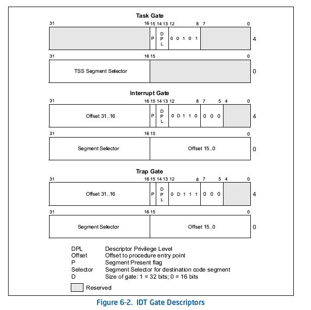
可以看出,一个表项占32*2位,8个字节。0到15位和48到63位为偏移量的低位和高位。16到31位是段选择子。 通过这几个数据来找到中断处理代码的入口。
7.2 初始化idt
中的SETGATE宏,填充idt数组内容。每个中断的入口由tools/vectors.c生成,使用trap.c中声明的vectors数组即可。1
2
3
4
5
6
7
8
9
10
11
12
13
14
15
16
17
18
19
20
21
22
23
24
25void idt_init(void)
{
/* LAB1 YOUR CODE : STEP 2 */
/* (1) Where are the entry addrs of each Interrupt Service Routine (ISR)?
* All ISR's entry addrs are stored in __vectors. where is uintptr_t __vectors[] ?
* __vectors[] is in kern/trap/vector.S which is produced by tools/vector.c
* (try "make" command in lab1, then you will find vector.S in kern/trap DIR)
* You can use "extern uintptr_t __vectors[];" to define this extern variable which will be used later.
* (2) Now you should setup the entries of ISR in Interrupt Description Table (IDT).
* Can you see idt[256] in this file? Yes, it's IDT! you can use SETGATE macro to setup each item of IDT
* (3) After setup the contents of IDT, you will let CPU know where is the IDT by using 'lidt' instruction.
* You don't know the meaning of this instruction? just google it! and check the libs/x86.h to know more.
* Notice: the argument of lidt is idt_pd. try to find it!
*/
int i = 0;
extern uintptr_t __vectors[];
for(i = 0; i < 255; ++i)
{
// vectors 中存储了中断处理程序的入口地址。vectors 定义在 vector.S 文件中,通过一个工具程序 vector.c 生成
SETGATE(idt[i], 0, GD_KTEXT, __vectors[i], 0);
}
// 切换用户模式到内核模式
SETGATE(idt[T_SWITCH_TOK], 1, GD_KTEXT, __vectors[T_SWITCH_TOK], 3);//
lidt(&idt_pd);
}
思路是:
- 通过SETGATE宏初始化idt表(这里体现为一维数组)
- 准备执行lidt指令,因为trap是系统调用,所以执行idt_init的时候是在DPL_USER(3)的模式,而根据实验指导书,lidt需要在DPL_KERNEL(0)模式执行,所以需要切换用户模式到内核模式
- 执行lidt,使用一个包含线性地址基址和界限的内存操作数来加载IDT
7.3 时钟中断
中断后,调用print_ticks子程序,向屏幕上打印一行文字”100 ticks”。
1 | case IRQ_OFFSET + IRQ_TIMER: |
思路是:每次 handles or dispatches an exception/interrupt都会调用trap,trap中通过累加tick这个时钟周期的全局变量(定义在clock.c)到100来触发时钟中断
8 小结
bootloader的启动到OS的加载流程为:
- 禁用中断
- 复位标志寄存器
- 初始化ds,es,ss三个段(设置为0)
- 使能A20(扩大寻址空间)
- 跳转到gdtdes中,加载GDT(全局描述符表)
- 使能cr0,切换到保护模式
- 切换到32位模式
- 修改保护模式下各个寄存器的值
- 设置堆栈以调用C,初始化栈区(0x0~0x7c00)
- 调用bootmain.c
- 运行bootmain,调用readseg读取多个扇区
- readseg循环执行readsect读取每个扇区
- 返回bootmain,判断elf格式
- 将ELFheader读入ph(pragram header,程序头表)
- 将ph中各个section读入内存
- 通过内核入口函数加载内核
总的来说实验量还是很好的,实验指导书也很到位,看项目级代码果然需要一个静态分析利器啊,感谢清华!